MUNDO METAL MECÂNICO

Elevador para barcos

Não é nenhuma novidade, mas sem dúvida é muito interessante! Boa leitura.
001   007
Falkirk Wheel
Complexo Millenium Link - Escócia

Engenharia:
Ove Arup & Partners - Butterley Engineering
 
Projeto de Arquitetura:
RMJM Architects
 
O Millennium Link é um ambicioso projeto de 84,5m de comprimento idealizado com o objetivo de
restaurar a navegação pela Escócia entre o histórico Forth & Clyde Canal e o Union Canal,
conseguindo assim um corredor que reativaria a atividade no centro da Escócia.
O maior desafio para alcançar esse objetivo era o desnível existente entre os dois canais:
o Forth & Clyde Canal está 35m (115pés) acima do nível do Union Central. Antigamente, os dois
canais eram conectados em Falkirk por  uma série de 11 eclusas distribuídas ao longo de
1,5 km, mas esta conexão foi desativada em 1933. Assim era preciso encontrar um método
rápido e simples, que conectasse os dois canais içando os barcos pelos 35m de desnível.
A British Waterways, apresentou uma solução visionaria aproveitando a oportunidade para criar
uma estrutura espetacular que com certeza seria perfeita para a comemoração do milênio, e um
símbolo para o futuro: o Falkirk Wheel - o primeiro elevador giratório de barcos do mundo.
Conectando dois canais com mais de 115 pés de desnível, o Falkirk Wheel é uma solução
inovadora que resolve o velho problema de transferir os barcos entre níveis diferentes.
O complexo foi o produto do trabalho conjunto da British Waterways, da Ove Arup Consultants,
a Butterley Engineering e o escritório de arquitetura RMJM.O design da Falkirk Wheel explora a
simplicidade da física, impondo o mínimo de energia necessário para girar uma massa fenomenal
de água e aço com graça e elegância. A grande Roda é movimentada por 10 motores hidráulicos
responsáveis pelo giro das duas gôndolas, que acomodam até 4 barcos de 20 metros de uma vez
cada uma, e possui a capacidade de levantar 600 toneladas de água a 35m de altura em menos
de 15 minutos.  
009        002
 
O PROJETO
   O Conceito original de usar uma roda para levantar barcos existe desde o século 19 na Europa, 
mas a primeira vez que foi considerado como uma possível solução para a Falkirk foi em 1994.
Dundee Architects e a Nicoll Russel Studios apresentaram a Ferris Wheel o primeiro design que foi
usado para atrair a participação da Millennium Commission Funding no projeto. O desenvolvimento
do projeto foi realizado por um consorcio liderado por Morrison-Bachy-Solentache e que incluiu o
escritório de arquitetura escocês RMJM Scotland Ltd. Este time remodelou o design original
da Roda. O maior objetivo de todos eles era de criar um elevador de barcos funcional que poderia
levantar e abaixar barcos levemente, celebrando a re-conexão dos dois canais históricos com
uma estrutura digna do novo milênio. As idéias e os conceitos apresentados foram muitos:
de ovos rolantes a tanques inclinados, de balanços gigantes a monotrilhos aéreos que incluíam
complexas estruturas de contra balanço. Mas a solução final escolhida foi o Falkirk Wheel, que
conseguiu combinar a função com o design, criando ao mesmo tempo uma elegante escultura.
 
 003  004
  006  008
  A forma única da estrutura parece ter se inspirado em várias fontes, tanto artificiais como
naturais, desde uma lança céltica dupla ou uma hélice de moinho ou de barco, até o
esqueleto de uma baleia ou a espinha de um peixe. O canal que conecta a Escócia de leste a
oeste como uma espinha dorsal, parece ter uma simbologia apropriada e há uma verdadeira
beleza no caminho do aqueduto. Os arcos sobre o aqueduto também adicionam um elemento
estético a estrutura, formando com seu reflexo no canal um circulo completo que aumenta a
sensação do túnel. O fato de o canal literalmente terminar no ar, cria uma excitante sensação de
estar "navegando no ar" de frente para o espetacular cenário do horizonte.
 
A CONSTRUÇÃO
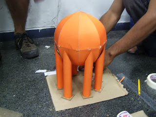
 As diversas partes do Falkirk Wheel foram construídas e montadas como um gigantesco
jogo de armar, na Butterley Engineering´s Steelworks em Derbyshire.
Ainda em fábrica foi realizada a pré-montgem completa das 1,200 toneladas de aço, ajustando
as peças com uma margem de erro de apenas 10mm assegurando o perfeito encaixe final.
 No verão de 2001, a estrutura foi desmontada e transportada em 35 caminhões para Falkirk,
onde foi realizada a montagem final no chão, das 5 grande seções posteriormente içadas
com um guindaste para ser colocadas na sua posição final.
A gôndola, com um total de 800 toneladas (somando peso próprio + água + barco), impõe
imensas tensões na estrutura quando se movimenta em volta da espinha central.
As soldas normais de aço seriam suscetíveis a fadiga induzida por esse stress, então para fazer
a estrutura mais robusta, as seções de aço receberam juntas aparafusadas.
Foram utilizados mais de 15.000 parafusos.
 falkirk_funcionamento  010 
 
011  012
__________________________________________________
Matéria Original no portal met@alica.com.br

Transporte de torre gigante para o Pólo Industrial congestiona Via Parafuso

Cm informações de Taynar Barreto/Cn1
Foto: Taynar Barreto/Cn1

Momento em que a torre desviava do Viaduto do Trabalhador e manobrava em frente ao HGC. Operários da Coelba levantam cabos de energia

O transporte de uma torre gigante que saiu as 6h, desta quarta-feira, 10, do Porto de Aratu com destino a empresa Oxiteno no Pólo Industrial de Camaçari, mobilizou varias carretas, equipes da Coelba e um aparato da Polícia Rodoviária e provocou congestionamento e trânsito lento durante todo o dia na Via Parafuso.

O equipamento veio de Taiwan de navio e por volta das 17h30 minutos conseguia desviar do Viaduto do Trabalhador, pois não passava por baixo de forma alguma. As equipes da Coelba a cada travessia de cabos de energia precisava eleva-los para que as carretas conseguissem passar.

Segundo informações, outros equipamentos semelhantes devem chegar nos próximos dias.
 

http://camacarinoticias.com.br/leitura.php?id=71556


Matéria interessante sobre turbinas hidraulicas:
Francis Turbine in Section

Introduction to the Different Types of Reaction Turbines Used in Hydropower

Hydropower is a source of renewable energy and is the only power source to have a stored source of energy, i.e. the reservoir.
The potential energy in the falling water is converted to kinetic energy by the water turbines which drive the generators to produce electricity.
There are two different categories of water turbines used by hydropower plants today, impulse and reaction turbines, which depend on different properties of the water supply to operate them. As we examined the impulse turbines in the previous article we will look into the operational characteristics of the reaction turbine.
So what is a reaction turbine? It was primarily designed to operate efficiently under conditions which supply water at a high flow rate combined with a low head. However, some hydrokinetic experts maintain this is the most versatile of all the water turbines with some coaxial turbines being a hybrid which can also operate under high head with high flow rate conditions
The reaction turbines can be propeller or coaxial radial flow types, and are very popular throughout the world. The Francis Turbine is a radial flow type of reaction turbine and is currently operating in the world’s largest hydropower plant at the controversial Three Gorges hydropower plant in China.
This is another article in my series on power from renewable energy, and a follow-up to my previous article on hydropower. In it we will look at the reaction turbine, examining the different types of turbines within this category which operate to give optimum efficiency to the hydro plant system.
So we begin then with the types of reaction turbines.

Types of Reaction Turbines used in Hydropower Stations

This category of turbines is used where sometimes only a low head of water is available but with a high flow rate, all these turbines are enclosed in a casing and submerged in the water supply. Listed below some of popular types of reaction turbines
  • Radial Flow Turbine
Francis Turbine
The Francis turbine is one of the most popular types of reaction turbine used in hydropower plants today, mainly because of its flexibility to operate very efficiently under high or low heads.
Water is introduced to the turbine through a spiral tube which is wrapped around the turbine exiting through curved adjustable vanes producing a coaxial water supply. When the water enters the turbine inlet it causes the water to swirl around the turbine blades, being of a radial contour and taper, towards the center of the runner in a vortex shape.
The water flows through the blades giving up more energy as it exits through a specially shaped draft tube. This acts as a diffuser from which water then flows out to the tailrace, having transferred all its converted potential energy and kinetic energy to the turbine.

  • Propeller Turbines
Kaplan Propeller Turbine
This is a popular type of reaction turbine once again totally enclosed in a casing, the blades being fully submerged in the water. There can be various numbers of blades, depending on the water supply properties and the particular hydropower characteristics
As the name suggests the blades are of propeller shape bolted onto the hub via component which enable the pitch of the blades to be altered.
The water inlet pipe is again in the form of a spiral tube wrapped around the turbine. There are adjustable wicket gates installed in the spiral tube, and these effectively convert the water from radial flow to axial flow onto the blades.
The combination of the adjustable wicket gates angle and propeller blades pitch gives the Kaplan turbine an efficiency of over 90%.
Bulb Propeller Turbine
The bulb turbine is rather unique as it has the generator enclosed in the water as well as the turbine.
It can be installed in the horizontal or vertical position and is fitted inside in a large tube supported by steel tie rods which maintain a clearance between the component and the pipe walls. The water flows into the tube from the penstock, over the bulb containing the power generator, and through the propeller turbine and exits into the tailrace. The power generation housing is designed in the shape of a bulb to minimise water friction, the generator and its electrical cabling being completely sealed against the ingress of water.
As well as being used in hydropower plants, bulb turbines are currently installed at The Rance Tidal Barrage Plant in France, and have been operating successfully since 1966.

Sketches of Types of Reaction Turbines

Bulb Turbine

Pictures and Flow Diagrams of Reaction Water Turbines

Kaplan Turbine ( electricalandelectronics.org)Francis Runner (www.ipmach.kharkov)Francis Flow (www.ipmach.kharkov.

Fonte : http://www.brighthub.com/engineering/civil/articles/66261.aspx#ixzz0yazjYY44